
Mechanical
Building this machine was a fun journey full of learning. I had to pick up new concepts and apply them directly to the system. Along the way, there were challenges and setbacks, but each version of the machine brought different outcomes and valuable experience.
Luna Plotter
The Luna Plotter began as a two-month research project, approached purely from an engineering perspective. The goal was simple: create a plotter with ATC for students. We experimented with several configurations, including one where a 4th axis acted as a tool changer. For this, we built a 28BYJ-48 stepper motor–based 4th axis that rotated to switch pens.
While promising in theory, the design proved impractical. Calibration was extremely difficult, and even a small shift created offsets. A 0.1–0.2 mm error is fine for plotting, but 1–2 mm is unacceptable. We eventually abandoned the idea and replaced it with a straightforward pen-picking mechanism. Like a conventional ATC, the machine simply moved to a fixed position and picked up the pen. It worked reliably without complications.
We tested the plotter during an inauguration event where it ran for six hours nonstop. This served as a strong trial, giving us both performance data and useful feedback from students.
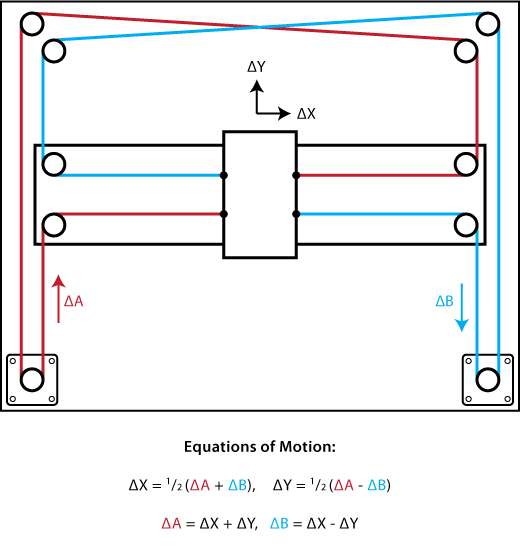
Core XY
For motion, we used a CoreXY kinematics. Large-format CoreXY systems were not very common at the time, but our tests showed it was effective. Its force balancing reduced vibrations and harmonics compared to other designs. In the final version, the machine reached speeds of 15,000 mm/min with acceleration up to 5000 mm/s².
Gantry
The gantry used bearings set at a 45-degree angle on V-slotted 20-series extrusions. Friction was higher than expected, but it functioned adequately. However, reliability dropped during extended use, as the bearings began creaking and the extrusions showed deformation. Still, it was a low-cost solution that worked well for the X and Y axes.
For the Z axis, we relied on a T8 four-start lead screw with a 6 mm shaft and linear bearings. Since the bed surface wasn’t perfectly uniform, a height-adjustment mechanism was required. A simple spring system solved this, allowing the Z axis to adapt to small variations.
ATC
The ATC was kept simple. A fixed position was assigned for tool changes, and the machine picked up pens with the help of magnets and 3D-printed parts. The setup was easy to implement and performed reliably.
Conclusion
Advantages
- High speed with reduced harmonics
- Easy to manufacture
- Low cost
Disadvantages
- Limited long-term reliability
- X and Y gantry prone to wear
With the first machine, we went into a meeting to define the new versions. There were two concepts: one based on CoreXY and another on Cartesian mechanics.
At the end of the event, we had a clear set of criteria for the next machine:- Maximum size limited to A3
- Switch to linear rails instead of the current system
- Add a keypad for control
- Include an ATC suitable for pens of different diameters
- Add a laser pointer for aligning the job to the work plate
- Ensure students can see the pen drawing from the front
So with that came the cantilevered machine
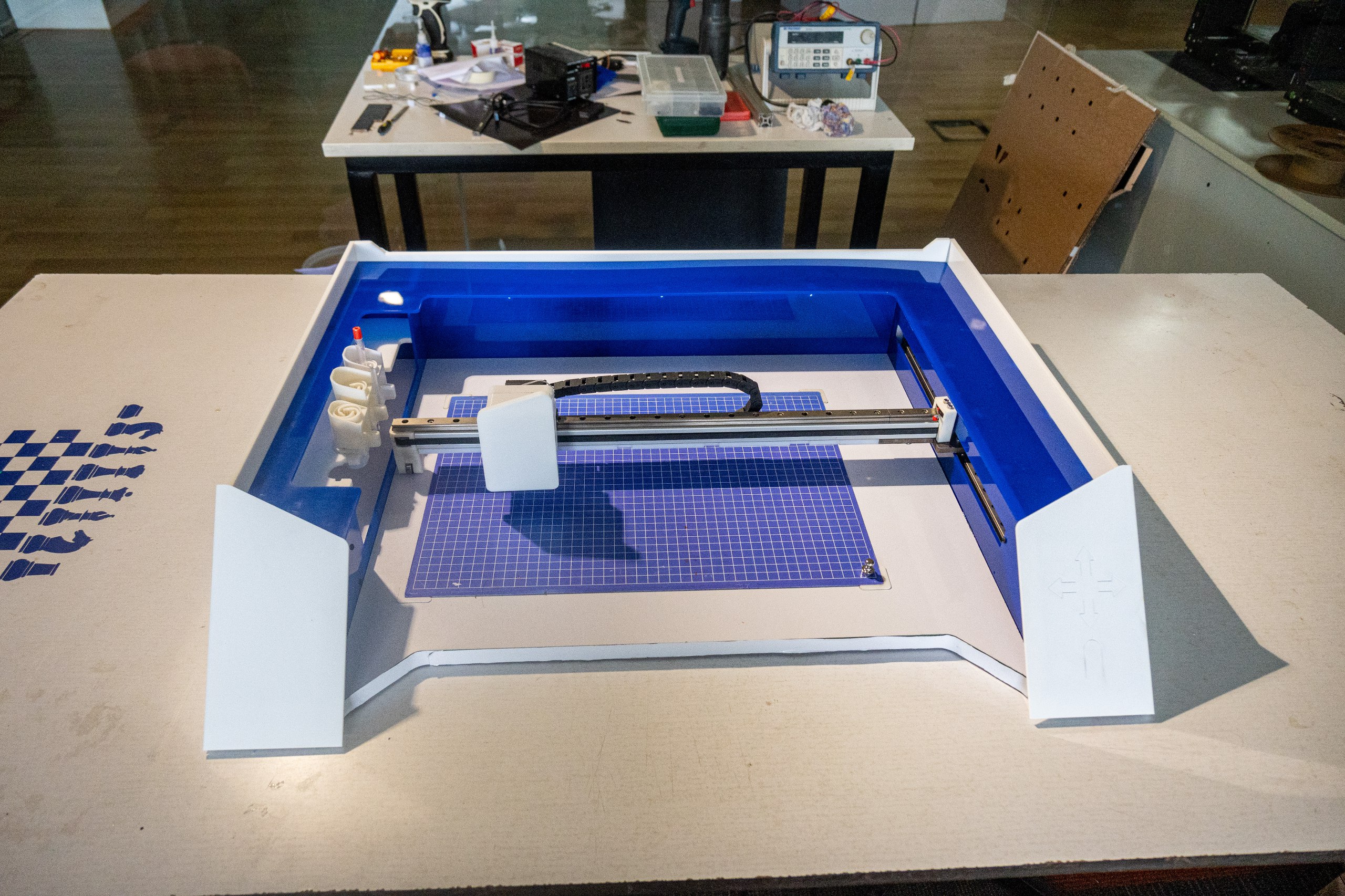
Cantilevered Machine
the cantiliverd machine was one of the machinw that was designed during the progress of the machine making it was an experience making acantiliverd machine i personally dosnt have any intreast in it but was fun to do it nevertheless
H-BOT
For the cantilevered machine, we used an H-Bot configuration because it was necessary to constrain the mechanism at one end and the ATC at the other end.
So, we derived kinematics for it. It’s a modified version of the H-Bot but constrained to a single side.
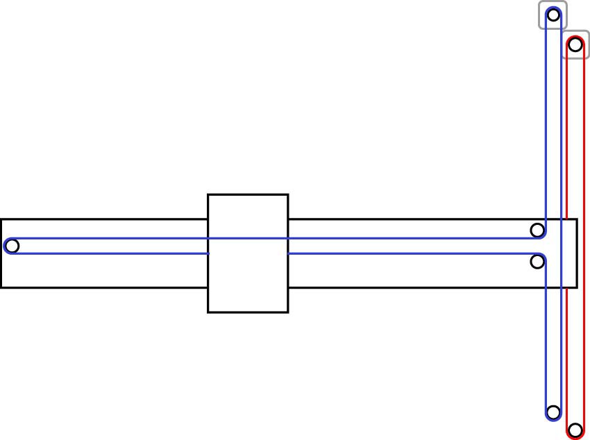
The kinematic equations for the machine are:
Δx =Δb − Δa
Δy = −Δa
Gantry
The gantry of the machine consists of linear rails for the X, Y, and Z axes. The gantry is cantilevered to the left end, and the motors and belts are placed at the right end of the machine. The Y-axis has two linear rails at the right end of the machine, spaced 80 mm apart, to stabilize the cantilevered gantry to an extent. The X-axis has a single linear rail with a drag chain to connect power.
The X and Y gantry are driven with stepper motors and belts, and for the Z-axis we are using capstan drives. The mechanism is simple: a pulley is connected to a servo with limits, which pulls the Z gantry up to 25 mm. The maximum gantry movement is constrained within the Z-axis servo’s limits, meaning the gantry moves from 0 to -25 mm when the servo moves from 0 to 180 degrees.
Cantilever
The machine uses a cantilevered gantry for the X-axis. The gantry was proposed because of the experience provided by the machine. The cantilevered design came with a single problem: angular error amplification. It amplifies the error from the right end to the left end. For example, if there is a 0.1 mm offset on the left, it can amplify to 1–2 mm, which is quite significant. To fix this, a calibration sequence at the right end was added to reach the desired height, along with calibration blocks to ensure there is no tilt in the X-gantry. Though challenging, it was still achievable.
ATC
The ATC of the machine had a requirement: it should be able to accommodate a variety of pen sizes from 9 mm to 13 mm, and when the pen is inserted, it should maintain its center point. For certain pens, a tolerance of 0.1 to 0.3 mm was needed because it is a plotter. A configuration of a flexure-based iris mechanism and PG13 connectors was used for this.
The tool changer is a magnetic-based mechanical latch without any electromechanical actuators. The Z-axis, sleeve, and pen holder have a protruded notch which locks into position with the help of magnets. The machine moves to the desired position to make the tool change happen.
Finishing
The electronics are focused at the back end of the machine and the left side. The ATC is at the front-left, and there is a keypad for movement and pausing jobs.
Pros and Cons
Pros
- The machine has high speed and acceleration: 20,000 mm/min speed and 10,000 mm/s² acceleration.
Cons
- Error amplification
- Harmonic vibration–caused errors
- Hard to calibrate